Project Longhaul
NOTE: If you link, please let me know. I would just like to know where this is showing up.
Once upon a time, a boy met a girl. Then a short amount of time later, the boy decided to design and build a ring for the girl, because doing things in the most complicated way possible is just what he does to show the love. This is that story.
It starts off in Jan of 2013 where the idea for the ring was refined to what will ultimately be the final form. Several designs were considered and were rejected because of exotic material requirements, machining geometry limitations or violating the laws of physics. It was a fun exercise to explore potential and unique designs, but at the end of the day, I still needed to make her something that I could present and that didn't look like it was carved with a spoon.
The final idea was to embed a LED and copper coil assembly inside the titanium ring, illuminating it from under the stones when it was in close proximity to an induced alternating magnetic field (henceforth called 'the transmitter'). Autodesk Inventor helped me develop all of the dimensions and constraints for the design. Having some help, I was able to obtain her ring size and the rest of the measurements were based from there (15.72mm if anyone was wondering).
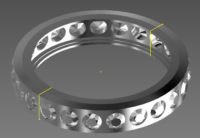
Figure 0 - Initial CAD Layout
A bunch of stuff happens from Figure 0 to Figure 1. See below for details!
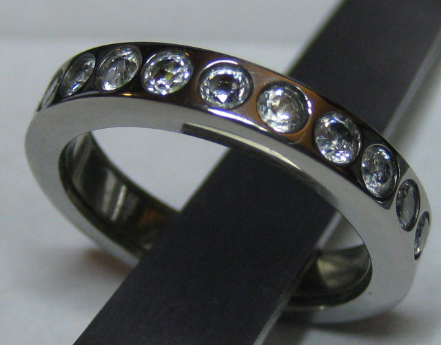
Figure 1 - Final ring
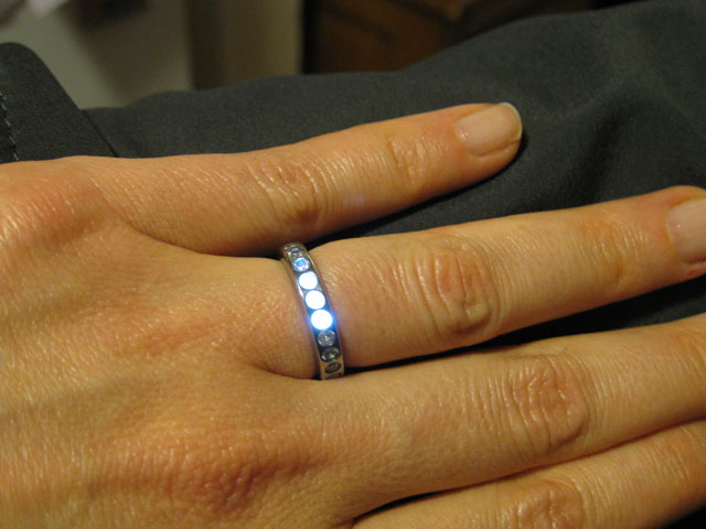
Figure 2 - With illumination goodness
The Details
Working with titanium was a little bit of a learning curve. Its harder than aluminum and steel which forces you to use carbide tools for any cuts. It is possible to use High Speed Steel tools but they wear out quickly, which will start to work-harden the cut. Someone with more experience could probably make it last longer, but I had to get this done!
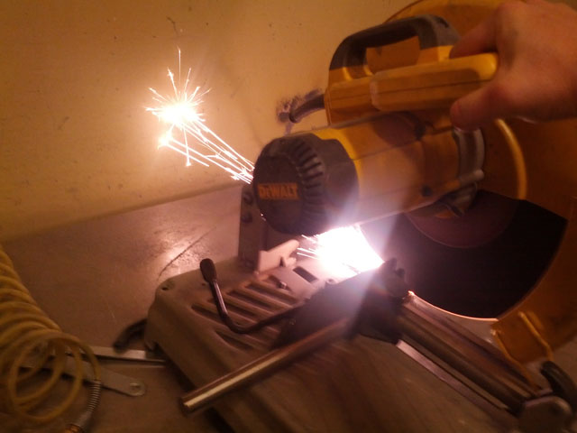
Figure 3 - First cut, bright white sparks
The ring start off as a bar of 0.875" diameter (apologies for mixing units) Titanium AL6V4. I face it off and turn down the external diameter to 19.8mm. This allows for 2mm of space on each side of the ring for all the features.
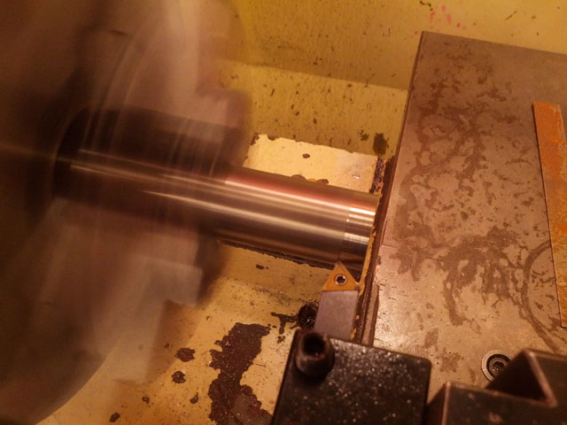
Figure 4 - Titanium bar faced and turned
The center hole is initially drilled with a spot drill to keep the larger carbide drill from wandering.
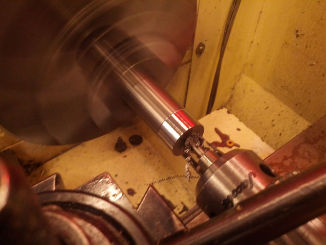
Figure 5 - Pilot hole drilled
Care needs to be taken to not overheat the drill bit (or any tooling for that matter). Titanium doesn't conduct heat well, so the heat will stay on the cutting edges of the tool. This puts the tool at a large risk for burn-up. As shown, this HSS drill bit died as a result of me getting it too hot and melting the outside cutting edge. First lesson to me: USE CARBIDE BITS
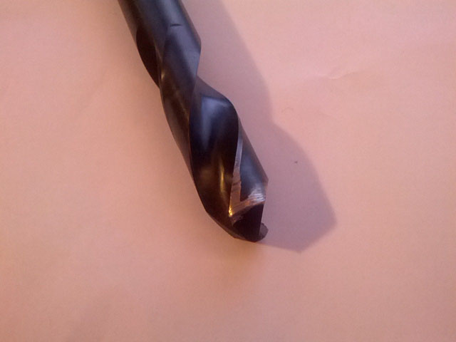
Figure 6 - First bit to die, edges melted
A boring bar is used to form the final hole to 15.8mm. This is larger than her size of 15.72mm, but since I am stuffing in electronics, I am making the diameter larger.
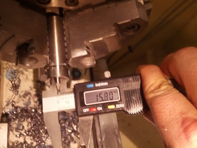
Figure 7 - Boring operation, final diameter
The 23 stone mounts were drilled on a mill using an index table in a 3 stage process. Stage one is to use a 0.8mm spotting drill to pilot the holes.
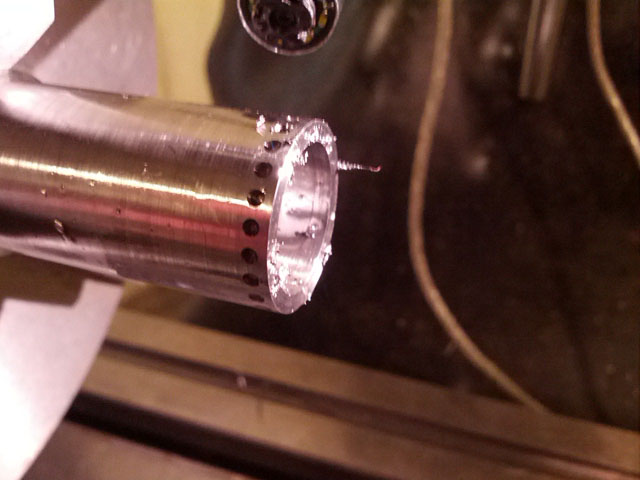
Figure 8 - Pilot hole drilling
A plunge hole drill of 2mm is to clear through the body of the ring is stage 2.

Figure 9 - Through-body hole
Then a 2.3mm drill was used to provide a seat for the stones for stage 3.
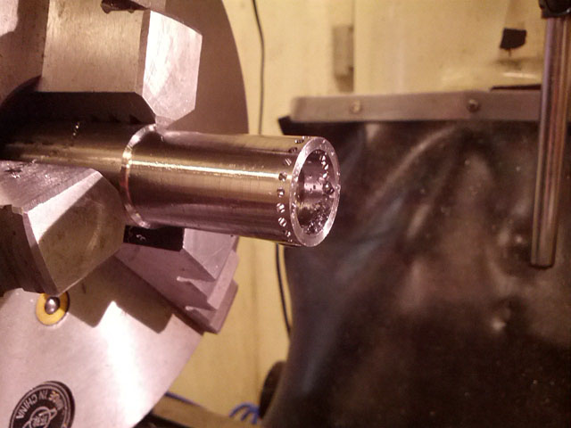
Figure 10 - Stone seat drill
Once complete, it is now necessary to separate the ring from the barstock. If we do not do it at this stage, the walls of the grove created in the subsequent steps will collapse.
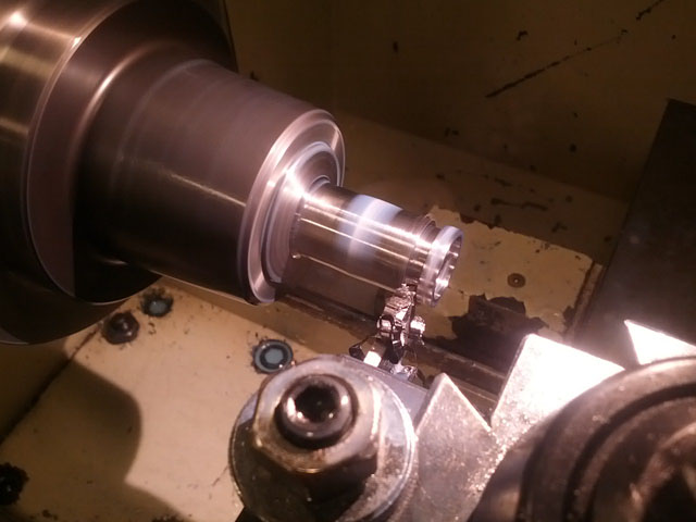
Figure 11 - Parting tool
A very small, thin and SHARP circle of metal accompanies the intended ring when it is cut off. Pro tip: not a good gift for children!
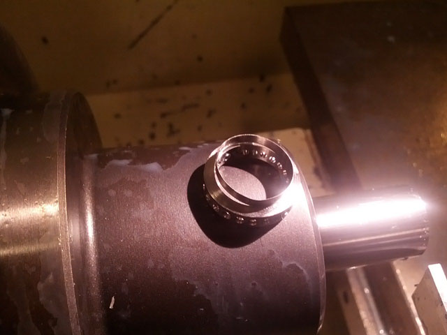
Figure 12 - Rough ring form
Now it is necessary to form the internal space for the electronics package. I use a collet on the lathe to hold a the ring, and a match-fit mandrel to help keep it aligned.
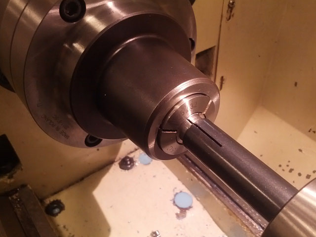
Figure 13 - Aligning the ring in the collet
Using an o-ring grooving tool, I carve out a 2mm x 1mm cavity within the ring. The shelf will hold the strip of permalloy (which will be explained later) and the space will accommodate the coil/LED assembly.
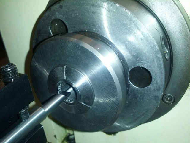
Figure 14 - Creating internal space
For reasons explained later, a slit will need to be cut into the ring. Cutting into a stone location will allow the stone to maintain the rings alignment, and keep it from bending. Should I have cut it between stone mounts, then it would be difficult to keep the ring from deflecting and causing a pinch point. A 0.006" saw was used to make the cut. Surprisingly, the slit saw was made from HSS, and held up really well. Remember to use your cutting oil, boys and girls!
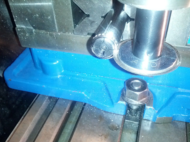
Figure 15 - Cutting the slit
The last stage of metal working includes the base polishing. This was accomplished in 3 steps, using a microscope. Since I took care on the lathe and the mill to use sharp carbide tools, the residual scratching was at a minimal. I used a 1200 grit sandpaper to remove any scratches that seemed 'big' to that grit. Then with the help of my dremel and felt wheels, I used the yellow compound followed by the white compound (on separate wheels). I was pleased with the results after I washed off the residual compound. I used the Ryobi Hard metal cleaning compound P/N: A04HM01. Thorough washing was required, allowing for a clean surface to which apply an epoxy.
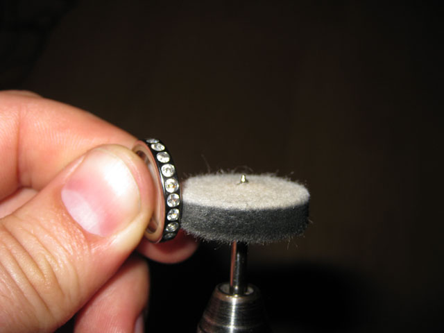
Figure 16 - Dremel polishing
I tried several attachment methods, but they all resulted in damaging the stones or ring. Since the holes were very close to the diameter of the stones, I opted to use jewelers epoxy (Epoxy 330, by Hughes Associates) to attach the stones to the ring. A holder was created to assist in this effort.
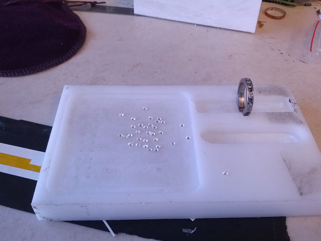
Figure 17 - Stone mounting jig
The stones were mounted 8 at a time, allowing the epoxy to cure between mountings. A quick touch-up with the white-compound buffing wheel, and the metal portion of the ring is completed.
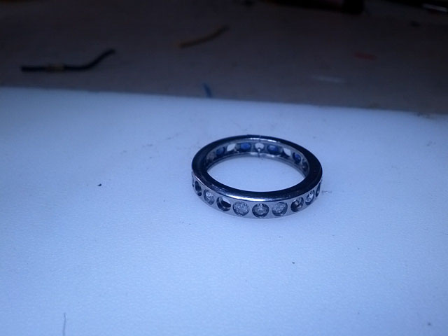
Figure 18 - Finished metal ring with (most) stones
The ring contains 13 white stones and 10 blue stones. Take note of the 'pin' stone at the location of the slit. This stone is under compression, helping it remain in its space.
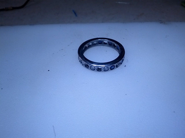
Figure 19 - The blue side
Electronics Packs
Creating the electronics packs was simple in theory. Create a coil of wire forming an inductor, add a capacitor and LEDs in parallel and TADA you have an inductive power receiver. To make sure that my wire and winding were aligned, I created a die with guides to assist in that effort.
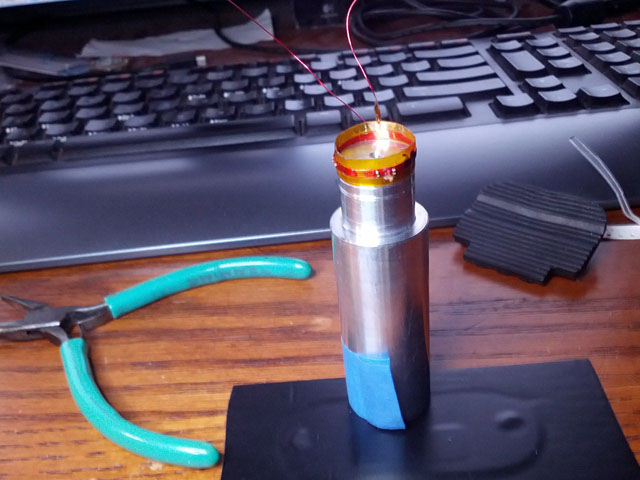
Figure 20- Coil winding die (with guide grooves)
Winding was tediously performed on top of Kapton tape, providing a sticky surface to adhere the 40-gauge enameled wire and an insulating layer to the rest of the ring.
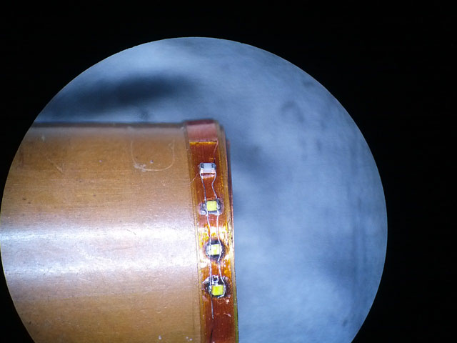
Figure 21- Coil closeup
The coil was measured to be approx 13uH. Adding in a 820pF capacitor brought my resonance frequency to approx 1.5MHz. ROHMs PicoLED series were used for the illuminators for their size and small power consumption. Heat resistant epoxy was used to affix the LEDs and capacitor to the kapton tape placed over the wire coil.
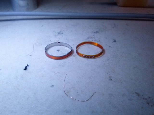
Figure 22 - Finished coil
The transmitter built was based off of a Marko Bakula design and slightly modified for my use. I increased the current handling of a few resistors, but largely its the same.
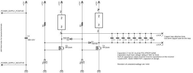
Figure 23 - Transmitter schematic
I opted to use a single copper plane board for design simplicity and current handling capability.
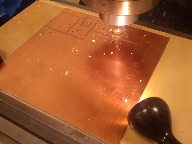
Figure 24 - Cutting transmitter circuit
A stiff and thick gauge wire was needed to handle the high AC voltages(80V p-to-p!!)and to keep from deforming, causing field irregularities. I wound the wire around round-cut 4x4, using a softer wire to maintain the spacing consistency. Once I stabilized the coils, I covered the whole thing in epoxy and wrapped the external diameter in tape to hold in the epoxy while it cured.
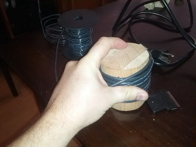
Figure 25 - Constructing transmitter coil
Removal was easier (and more destruction-y) than anticipated. After drilling a lot of holes in the block, I simply broke and knocked loose the segments, leaving the coil in tact.
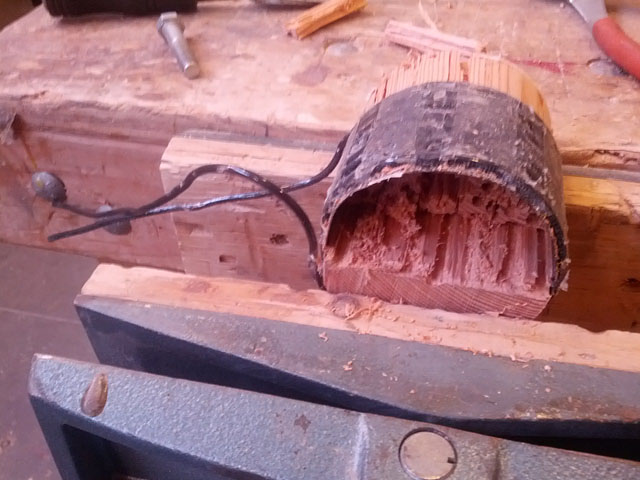
Figure 26 - Removing transmitter coil from the form
Soldering the large inductor coils to the transmitter circuit required a big iron and a lot of heat, but it didn't seem to damage anything. The board was attached onto an armband so that I could affix it to my forearm.
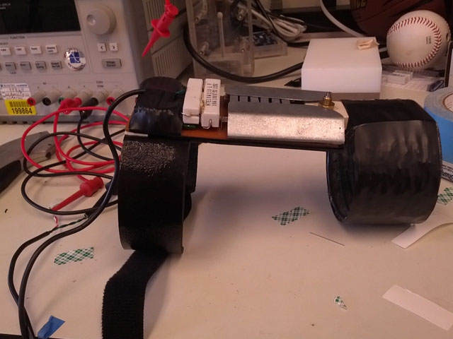
Figure 27 - Armband transmitter
The jacket test was to conceal the transmitter under the jacket so that it would illuminate when I got close to her hand.
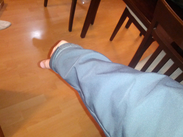
Figure 28 - Transmitter concealment test
Ring Assembly
Initial tests show the field effectively coupling from the transmitter to the ring, illuminating the LEDs. A Permalloy core helps re-direct the magnetic field allowing for more of the field to couple into the coils of the ring.
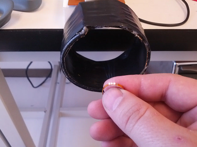
Figure 29 - Ring illumination
Care had to be taken while stuffing the coil into the ring. When I first tried it, I apparently forgot how induced magnetic fields cause currents within a metal ring, causing the field to cancel out of the intended inductor coil. This is why a slit is required in the titanium ring.
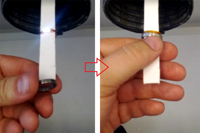
Figure 30 - Ring el no work-o
A video showing the uncut ring screwing up the works.
Video 1 - d'oh!
The permalloy strip was difficult to fit, since it was such a tight fit and I had no real way of precisely cutting the strips. Sanding was performed to fit the strip into the groove. Once the strip was fit and epoxied in, a final polish was performed to remove any stray marks made during assembly.
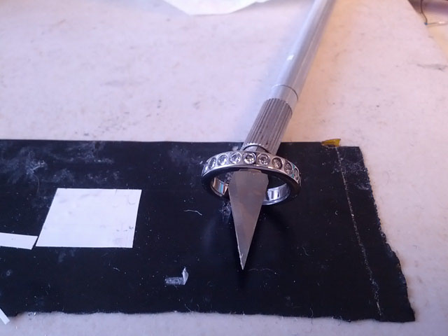
Figure 31 - Final ring
Ring in action!
Video 2 - Light!
Design Problems and Challenges
Of all the challenges presented in making the ring, affixing the stone is the most difficult. Traditionally, stones are affixed by mechanical means -- prongs, groves or snaps. Epoxies will delaminate from the attachment surfaces due to microstresses, thermal cycling, and other unmentioned movements. The stone may be attached now, but eventually it will fall out. It's just a matter of time.
With that in mind, I had 4 initial ideas for affixing the stone: thermally expanding the hole, hole deformation, point expansion deformation, and epoxy. Ultimately, I went with the epoxy method for attaching the stones.
The first test was to try and heat the ring, expand the hold and drop in the stone. When the hole cooled and contracted, it would hold the stone in place. Not only does the hole not expand enough, if I was lucky enough for it to happen (it did once), the stone would fracture along pre-existing crack lines.
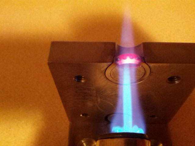
Figure 32 - Thermal setting: Fail
Next I was attempting to deform the top of the stone mounting hole, 'mushrooming' the metal, holding it in place. This would be achieved by a negative-angle hole punch fabricated out of tool steel, somewhat similar to a leather hole punch.
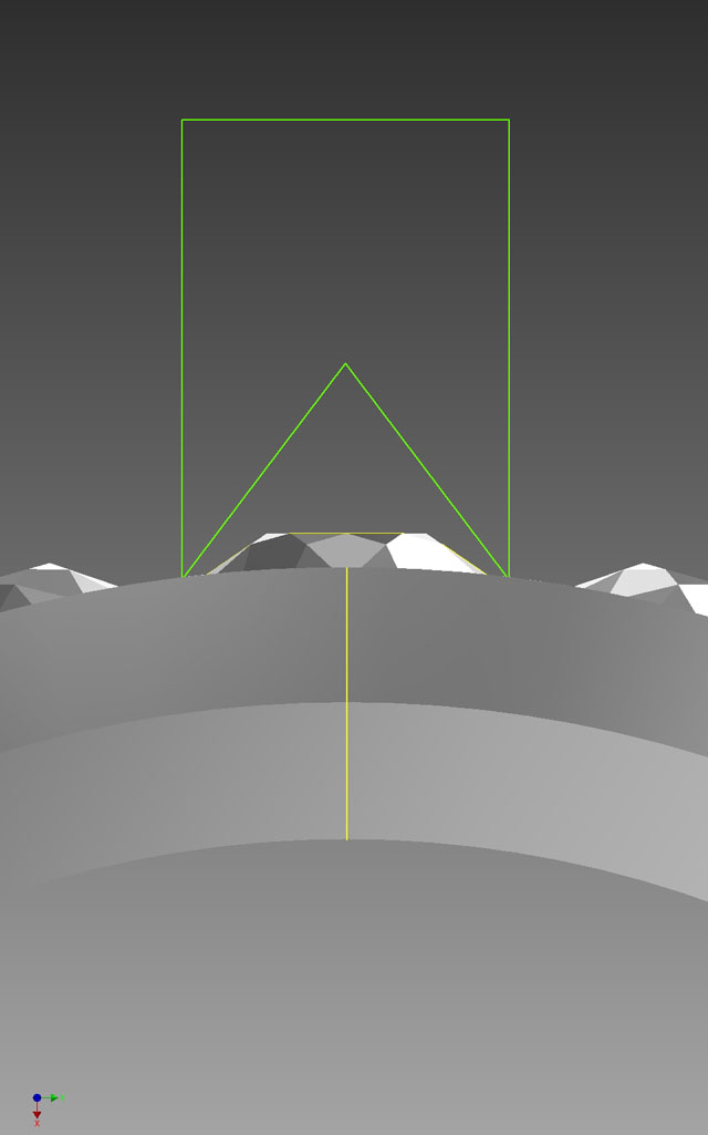
Figure 33 - Hole mushrooming idea
The failure mechanism is that it CRUSHES the stone to dust. When I disturbed the compacted dust with a probe, it all fell out the bottom of the hole. The bar is a drill blank, made out of tool steel that was ultimately made into the hole punch. I bent and fractured it when performing the press trial.
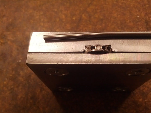
Figure 34 - Hole mushrooming idea: Fail
Third in line for stone attachment was to use a punch to press holes in 4 corners, deforming the metal in controlled ways, affixing the stone at discrete points.
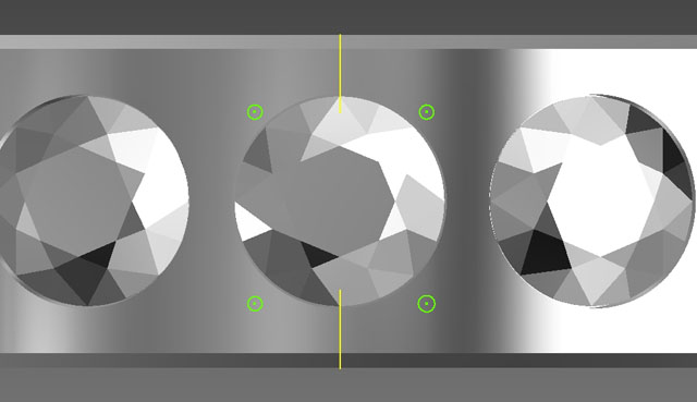
Figure 35 - Point expansion idea
Titanium apparently does not like to be stabbed, because the ring fractured axially.
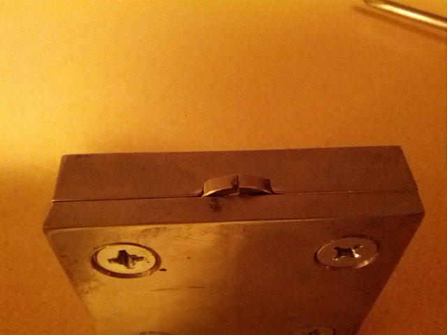
Figure 36 - Point expansion idea: Fail
Other design points of interest
I started this idea in January 2013, and presented the ring to my fiancée on May 2013. From the start, I had to learn AutoCAD, design and develop a circuit that would inductively couple power to the ring, and also how to understand the nuances of working with titanium. In that time, I made several test models and explored several options before coming to this design. The presented ring represents version 10 of the cut metal rings. The previous 9 models were stepping stones to understand behaviors, or test out theories of how to perform an operation. A good scientist knows to do qualitative tests! The most recently made ring (ver 10) is on the left. The top bar is titanium rod that was used as the ring base. The smaller rod is the aluminum that was used for initial drilling and sizing tests.
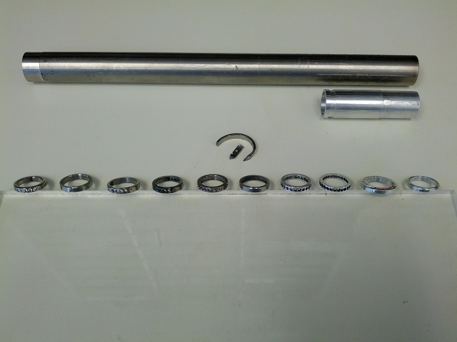
Figure 37 - Ring test versions
Follow-up
So, the original plan was to present this ring to the girl, then take her to a professional jeweler the next day to pick out something more permanent. Well, she insists that I change the design on this ring to make it more permanent and forgo a professionally made ring. There was a small hitch with the ring as shown above. Due to a small miscalculation, the internal diameter is now about 15.6mm, which is a really tight fit for her 15.72mm finger. I was able to cut a new ring and mount the remaining stones for a more comfortable fit. So in the near future, she will be wearing this ring while I work on a permanent design.
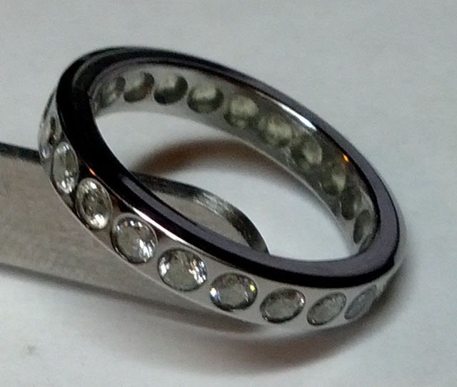
Figure 38 - Semi-permanent ring
I would like to thank several people for helping me when I was in my moment of 'Now, HOW do I do this???': Tony Giannetti for help with flushing out initial design ideas, Seahyaan Desai for being the material scientist I needed at the crucial time, Jon Maiara for helping me through some of the e-mag equations, Jeremy Swerdlow for relating some of his build experiences, The TechShop for having the tooling available to make it all possible, and to my new fiancée Julie; Thank you for being my inspiration!
Last updated May 19th, 2013 - Copyright Enfinicorp.
Page maintained by: benkokes@hotmail.com