Primary and First cascade stages shown. The 555
shown controls the overall on/off of the sign |
 |
L.E.D. Marquee
This page will change in accordance with hardware updates.
NOTE: If you link, please let me know. I would just like to know where this is showing up.
Background: While attending California State University Fresno's computer engineering program, a display was donated by SMC that showcased one of their programmable microprossors. In addition to other visual displays, this spelled out the letters S M C that were embededed onto the circutiboard with surface-mount leds. I thought it would be a fun idea to implement a similar idea in a more personal way. So I decided to build my own lighted nameplate.
Parts:
Depending upon the message you wish to display, your specific 74LS164 and LED quantities will vary. To make my name "Ben Kokes" I used the following:
(9) 74LS164 - Serial-in , Parallel-out shift register. Datasheet for the 74LS164
(85) Green LED's.
(85) Resistors. These are for current-limiting the LED's. I used 110 ohm resistors.
(2) LM555 timers. Datasheet for the LM555
(3) Capacitors for the LM555. These values are dependent upon the behavior you wish your sign to have.
(6) Resistors for the LM555. Again these values are dependent upon the behavior you wish your sign to have.
(1) Diode.
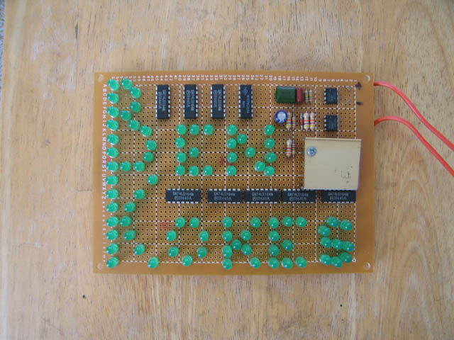
Extra Parts: Under the heatsink on the right, is a voltage regulator. The two resistors to the immidiate left of the heatsink are to set the output value of the regulator. In this document I will not get into that part of the circuit because (1) its an easy little calculation, and (2), I forgot to take the heatsink off and take a picture of the component and I forgot the exact one I used. I do remember I got it from radioshack, so I suppose any ol' regulator will do as long as it puts out 5 volts and can handle at least 1000mA.
Construction:
The design is relatively straight-foreward.One of the 555's set the rate you wish the individual LED's to turn on ( and off). I set this at a 50% duty cycle so it looked like the "spelling" of the word looked uniform. The other 555 sets the rate at which the turn on and turn off sequence begins. I used a skewed rate to keep the name lighted longer that when it toggles to its off cycle. These two 555's are entirely set-able depending upon the behavior you wish to have.
The device utilizes a cascading concept. The 555 starts off the first 74LS164 with a HIGH signal to pin 1, which sequentially shifts high the outputs Q0 thru Q7 ( pins 3-6, 10-13) at the clock pulse. Cascading the signal is as easy as tying the final output Q7 (pin 13) in your 74LS164 to the input (pin 1) of the next 74LS164.
Primary and First cascade stages shown. The 555
shown controls the overall on/off of the sign |
|
Timing IC (555) connections |
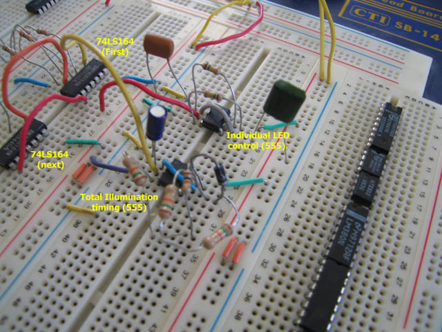 |
Primary and 1st cascade chip. Subsequent cascade stages
are just added on identically to the 1st cascade. |
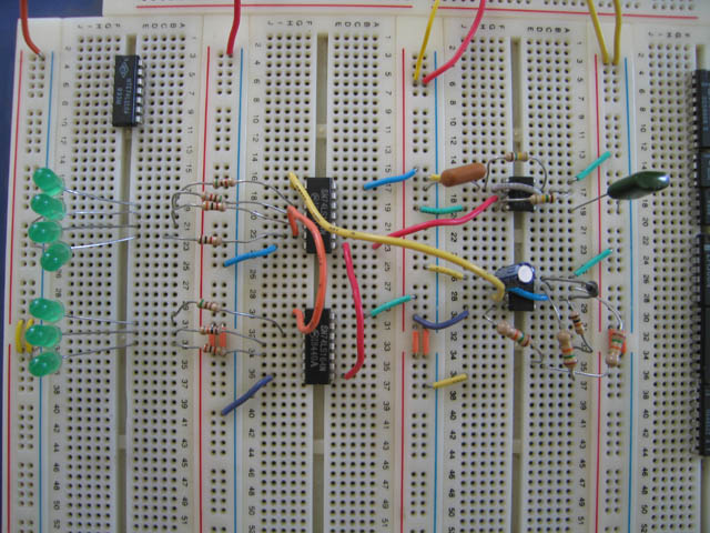 |
At this point, the number of cascaded stages is entirely dependent upon the length of your message. I figured out how many LED's I needed for my name before I decided on how many cascaded stages I needed. Except for the "B" and the "K", every LED has its own output from the 74LS164's. For the "B" and the "K", I decided to have it turn on in 'levels', so that one output was driving 2 to 3 LED's. This made the "B" and the "K" a bit dimmer, but within acceptable limits for me.
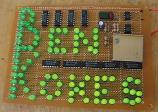
The front. The gold patch is a heatsink that is hiding
a voltage regulator |
 |
The back. Notice the current-limiting resistors. Also,
the tubing is teflon, not plastic. |
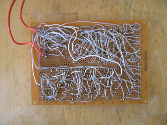 |
As for the back, this was obviously the most time consuming. Except for a few wire connections(that are shown in white and orange), I had to basically insulate my own wires. The clear coat on most of the wires is teflon tubing. I couldn't use plastic because of the tight spacing. The soldering iron would touch the plastic and melt it, so I had to use teflon. This proved time consuming because as the tube was cut to length with a pair of wirecutters, it would pinch the end of the tube closed. I has to use a push-pin to open the tube back up so that I could slip the bare wire inside. I think next time, I will use sockets for the IC's just in case one goes bad.
| Click image for video |
 |
Last updated June 16th, 2006 - Copyright Enfinicorp.
Page manitained by: benkokes@hotmail.com