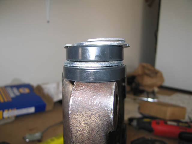
Shim, bearing, retainer order for input side.

Power Steering Gearbox Rebuild
This page is always under construction.
NOTE: If you link, please let me know. I would just like to know where this is showing up.
A few weeks ago, I decided to rebuild my ancient power steering box for my 1973 Bronco. This is a factory power steering box, so parts for this little guy are extremely rare. My first attempt netted disastrous results. I damaged a teflon ring which didn't allow pressure to build up to develop power assist, with addition of a small bearing that snuck out of the screw-path and did a little damage. Needless to say, I was distraught and sent it out to Lee's Manufacturing in Sun Valley, CA (https://leepowersteering.com) for repair. His standard service cost is reasonable, but with the extent of the damage, it was more expensive to repair my power steering box than to buy a newer, stronger box from West Coast Broncos. $35 later, I had a fully disassemble power steering box in my possession. I decided to try a rebuild one more time with the Napa rebuild kit and see if I learned from my mistakes.
First to note, the instructions for the Napa kit are absolutely HORRIBLE. I was able to piece together a procedure for my specific rebuild. First and Foremost! SOAK THE TEFLON RINGS IN BOILING WATER. and MAKE SURE they arent touching the bottom of the pan as they boil, they could melt. I melted one of the old rings when I was doing a test-boiling. Good things for tests. 5 minutes of soaking should do, you are just heating them up to allow them to be a little more elastic. Stretch too much and they will stay too large. Use a dental pick or some very small piece of metal (about the diameter of toothpick) to try and fit the teflon rings to their respective locations. This will help you keep the rings small with minimal stretching.
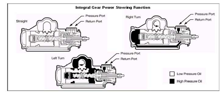
This page is intended to be an addendum to the rebuild instructions that are found here: http://www.chevelles.com/techref/shea_2.html. I will try to host them locally just in case the link goes dead. A pressure diagram can also be found here: www.kokes.net/bronco/ps_pressure.jpg. It outlines the pressure circuits when turning left and right.
|
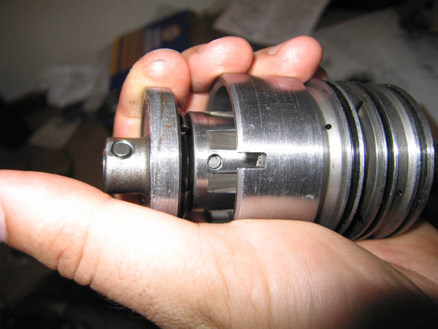
Shim, bearing, retainer order for input side.
|
|
|
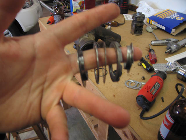
Since my box was already in pieces and the diagram from the Napa rebuild kit was garbage, I had to figure out the order on my own. The pieces in this kit are all relatively different if you pay close enough attention. Shown here is the order in which you reassemble the parts onto the cap for the input (facing the driver) side. In the background, you can see the piston, next to the Napa parts box.
|
Valve body o-ring.
|
 |
Now at this point, I would recommend using a thick lubricant, such as petroleum jelly, it will help this part slide into the body. Its a tight fit, so be careful not to shear the o-ring
|
Input shaft into valve body alignment.
|
 |
 |
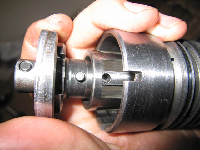
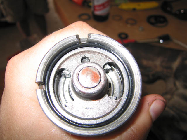
Its important to line up the little nub on the input shaft and the hole in the valve body as you slide them together. The whole assembly is tightly machined, so if you are able to somehow superman them together without lining them up, you may need another assembly. Else, it will just stick and the flat end of the input shaft (shown on left) will not fit into the valve body ( long fat cylinder on right with the 3 grooves)
|
Valve Body O-ring, large.
|
 |
The output shaft top should fit snugly inside the valve body. The o-ring should fit as shown. The diameter of the o-ring may seem a *hair* too large, but just use a little petroleum jelly to hold it down.
|
"Screw" shim and bearing order.
|
 |
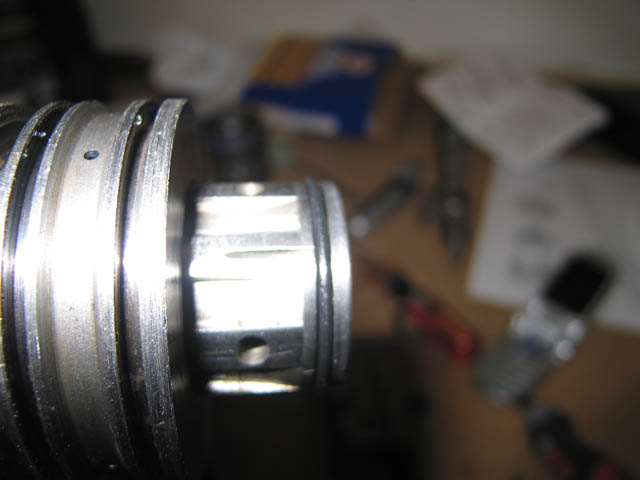
This is the order of shim-bearing-shim for this screw-shaft. This is installed into the housing before the piston is installed. As you can see on the right-most side of the shaft, you can see a white spot where the shaft is damaged. If you aren't careful reinstalling the loose ball-bearings, one will get free and do more damage than is shown. I was lucky for it to do such little damage. Liberally (not fill) use petroleum jelly on the threads of the screw. This will help you install the loose ball bearings.
|
Housing with upper support bearing and piston installed.
|
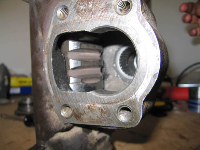 |
As you can see, within the housing, the upper support bearing is installed so that it is just below being flush with the housing at that point. The gear teeth you see on the left within the housing is the piston.You will need to reassembe the input-shaft portion before installing the sector shaft so that you can turn the piston and install the loose bal bearings. The sector shaft has not been shown on this page, because frankly I forgot to take a picture of it. There are 3 shafts for this box. One that connects to your steering wheel shaft, one that looks like a screw, and one that connects to the pitman arm at the bottom ( closest to the ground when installed into the vehicle) of the power steering box. This third shaft (which is also the largest) is the sector shaft.
|
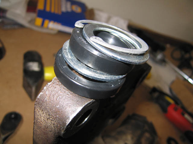
Lower seals for sector shaft
|
 |
 |
Before you install your sector shaft into the housing, I would recommend installing the lower shaft seals so that you do not have to worry about damaging the shaft. I found that there was a lot of room for the seals, and quite a bit of space between the retaining ring and the installed seals. I discovered that this is ok and the seals will have some wiggle room if they want. With the bottom of the box pointing towards the sky (the small, circular end that is) Install the seals in the order shown. First to go in is the thinner seal, then a shim, then the fatter seal, then another shim and finally the snap ring.
I hope this document has helped you through some of the more confusing elements of a power steering box rebuild. The remainder of the initial install document should be sufficient to guide you through the remainder of the rebuild. Should you have any questions, feel free to email me at benkokes@hotmail.com.
Good luck and happy wheelin'
Updated June 15, 2006 - benkokes@hotmail.com