iPod
GPS
This page will change in accordance with hardware updates.
NOTE: If you link, please let me know. I would just like to know where this is showing up.
About two years ago, while working for the now defunct GPS company - Nemerix, I decided to make a little application to showcase the low-power ability of the GPS.
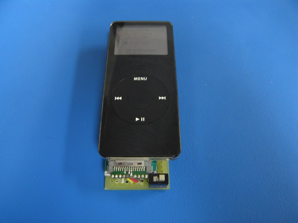
Combining a reference design board containing a Nemerix GPS with an Atmel ATMEGA324 micro-controller (and of course assorted supporting components), I had the hardware tools to spit-out data to the iPod. However the iPod will not accept just any serial data stream. The data has to be formatted to display on the iPod screen, which made this project a challenge and appealing to me.
Figure 1: Overall iPod assembly.
Frankly, the hardware portion of this project is not at all that complex. The reference design board from Nemerix contains the RF goodies to decode the satellite range and Doppler. An ARM7 does all the math crunching to be able to spit out NMEA data over a UART channel. Nemerix was split up into 3 locations across the world at the time of the iPodGPS construction (HQ in Manno-Switzerland, Software Dev in Cambridge-UK, and R&D in Santa Clara, California). That being said, I did not have access to the code contained in the ARM7, so I needed a secondary processor to convert the NMEA data to something the iPod could understand. Enter the Atmel ATMEGA324.
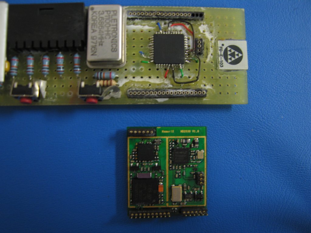
Figure 2: Close-up of Atmel and GPS module
The Atmel was chosen because it had 2 UART ports. One port for the incoming NMEA data and one port for the outgoing iPod data blocks. The other components on the board were supporting elements. A Fractus antenna (which is in dire need to be tuned to my application) battery, resistors, a few switches and of course an iPod connector which was cannibalized from a $2 fire-wire cable I found at a junk store. Unfortunately the whole device requires about 48mA of current, and the iPod could only supply about 25mA. A battery was needed.
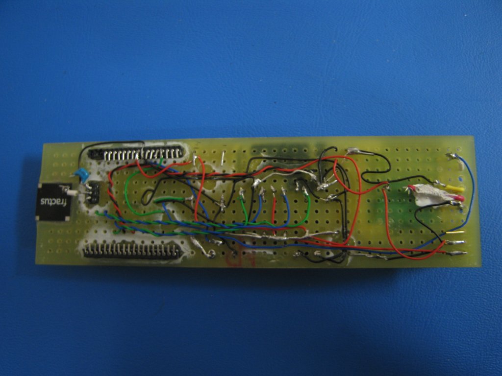
Figure 3: Back of board
Frankly, the hardest part of the project was the firmware for the Atmel. Not only did I have to figure out how to synch between two UART ports, I had to make sure the iPod was happily listening to my serial stream I was sending it.
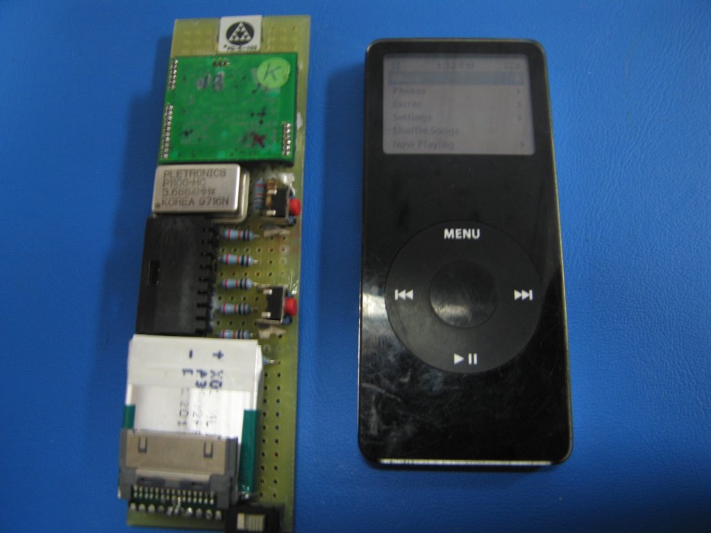
Figure 4: Full board
My Firmware takes advantage of the AiR mode that has been developed for iPod. The AiR mode allows the user to send a 4-color picture to the iPod and display it on the screen. Alpine and BMW showcased this ability when iPod was to be integrated into their new (at the time) cars. VERY basic information regarding the functionality of the AiR mode existed on the web, and left it up to the user to figure out the rest. I was able to obtain an old alpine unit, sniff the serial stream, and fill in the details as needed. At the time of this writing in April 2009, a decent explanation of commands for the iPod exists here (which didn’t exist at the time of construction): http://www.adriangame.co.uk/ipod-acc-pro.html
Basically I wrote a screen driver that builds a picture and sends it to the iPod. This was a VERY long and involved process which had some trial and error. Thanks to the grid layout of my Engineering Green notepads, I had the idea of building each character as a block and just draw specific pixels in each block. That way I can develop a character set to display on the screen.

Figure 5: Grid Screen method – 5 blocks.
So following that method, built a driver that handles all ‘graphics’ in terms of blocks. Unfortunately, I had to figure out each display character in my intended set. Naturally I had to have 0 through 9 and a radix point to be able to display the Lat/Lon output messages. Also I had to develop each letter to be displayed as well, so naturally the alphabet is somewhat limited to “L” “A” “T” “O” “N” ;-). I arranged each block in a 3-dimensional array. Therefore, when each line of the screen was to be drawn, it is possible to just call the firsts element of the array for the specific letter/number, and then let the graphic construction algorithm do the rest of the work for me.
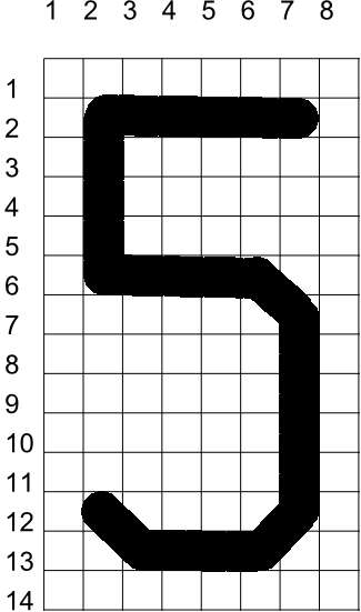
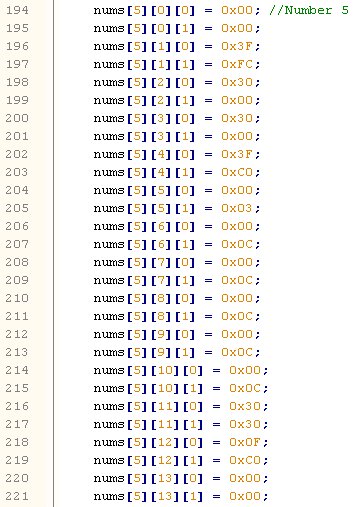
Figure 6: Specific outline of Character construction and corresponding code.
Building the Characters were pretty straight forward. Every cell in Figure 6 - left, represents a pixel. There are two bits per pixel (4 color - white, two grays and a black). The array fields are straight forward as well:
nums[the_intended_number][specific_row][left_byte_or_right_byte].
The array construction was initially intended to only handle numbers, and I intended to address the array by the [the_intended_number] element. However as I got more complex with the program, I added letters as well. Fortunately, the text is static (such as LAT or LON labeling) and I didn’t have to deal with writing an algorithm to convert a Letter into a Number to use my ‘font’ library. The numbers, on the other hand, are being continuously updated from the GGA message and I can plug them directly into the [the_intended_number] element to specify the specific number to use.
Once I was happy with the way the iPod displayed static data, it was on to the next task of receiving data to the micro-controller, decimating it and pulling out the pieces that mattered to me. For the task of receiving things over the UART, I happily used and modified Peter Fleury’s http://jump.to/fleury UART libraries. They can still be found on http://www.avrfreaks.net website.
Basically I was looking for the incoming GGA message that contains the Latitude and Longitude information from the GPS receiver. In the Nemerix chipset that I possessed, the string was terminated with an asterisk “*” and checksum. Once the asterisk was received, I would shut down reception of any further NMEA messages but disabling the UART. This was to prevent any overwrite in the ring buffer. After disabling the UART, the algorithm would start the decimation of the Lat and Lon measurements.
$GPGGA,032454,3722.8115,N,12158.052,E,1,06,2.2,18.3,M,39.0,M,,*CS
Figure 7: Typical GGA message (with terminator)
Once the Latitude and Longitude was broken down into their individual digits, I would use this data to directly control the specific graphic block to be displayed on the iPod. The UART was re-enabled and the assembly of the screen display would begin. Each ‘picture block’ could only contain a finite amount of data. In this case, I could only send approximately 512bytes at a time to the iPod. So the entire display would have to be sent over 3 blocks. I ran into an issue where the micro-controller CPU could assemble the screen display faster than what was possible for the output of the UART (at a screamin’ fast 56700kbps), so regular, multiple wait states had to be inserted to ensure the ring-buffer wouldn’t overwrite data contained within it.
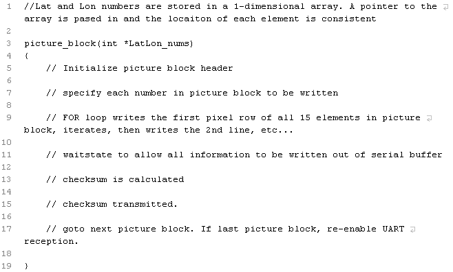
Figure 8: Code diagram of blocks and approx wait states.
After some trial and error, I understood the approximate minimum time needed to delay before the next block of data could be transmitted. Inserting wait states is horribly inefficient, but if I need to get it onto a smaller micro-controller, I can come back and figure out how to do it more efficiently. The entire screen update rate is approx 1Hz.
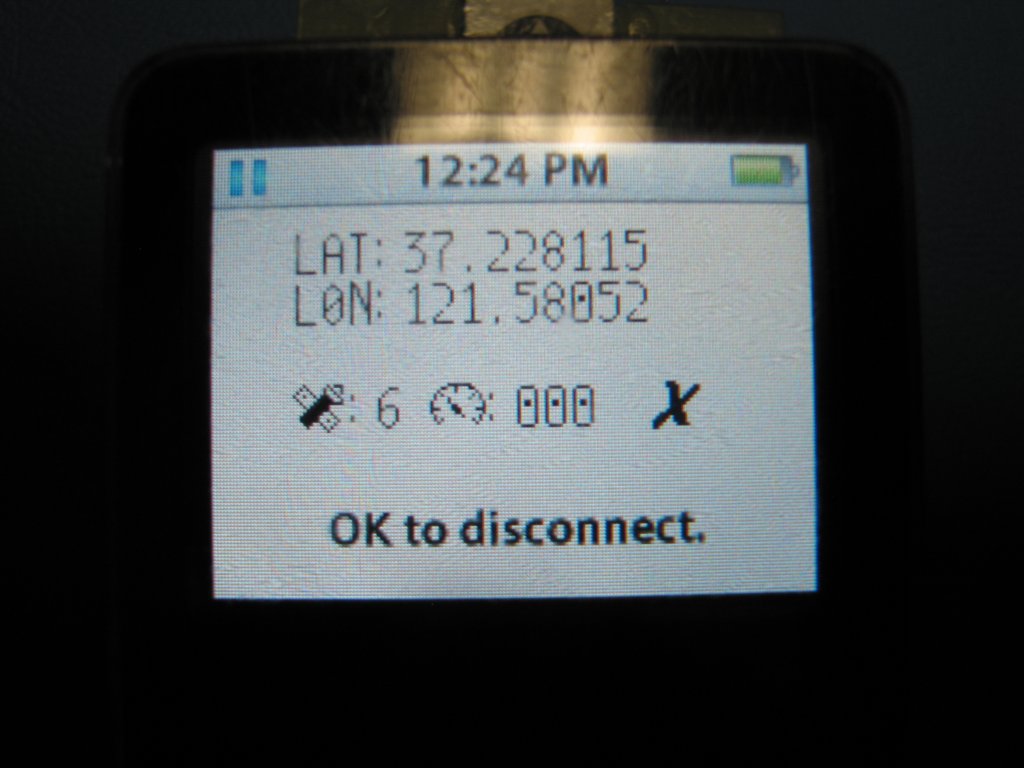
Figure 9: Screenshot of working code. Bottom middle is intended to be Velocity.
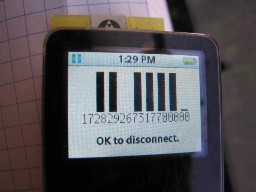
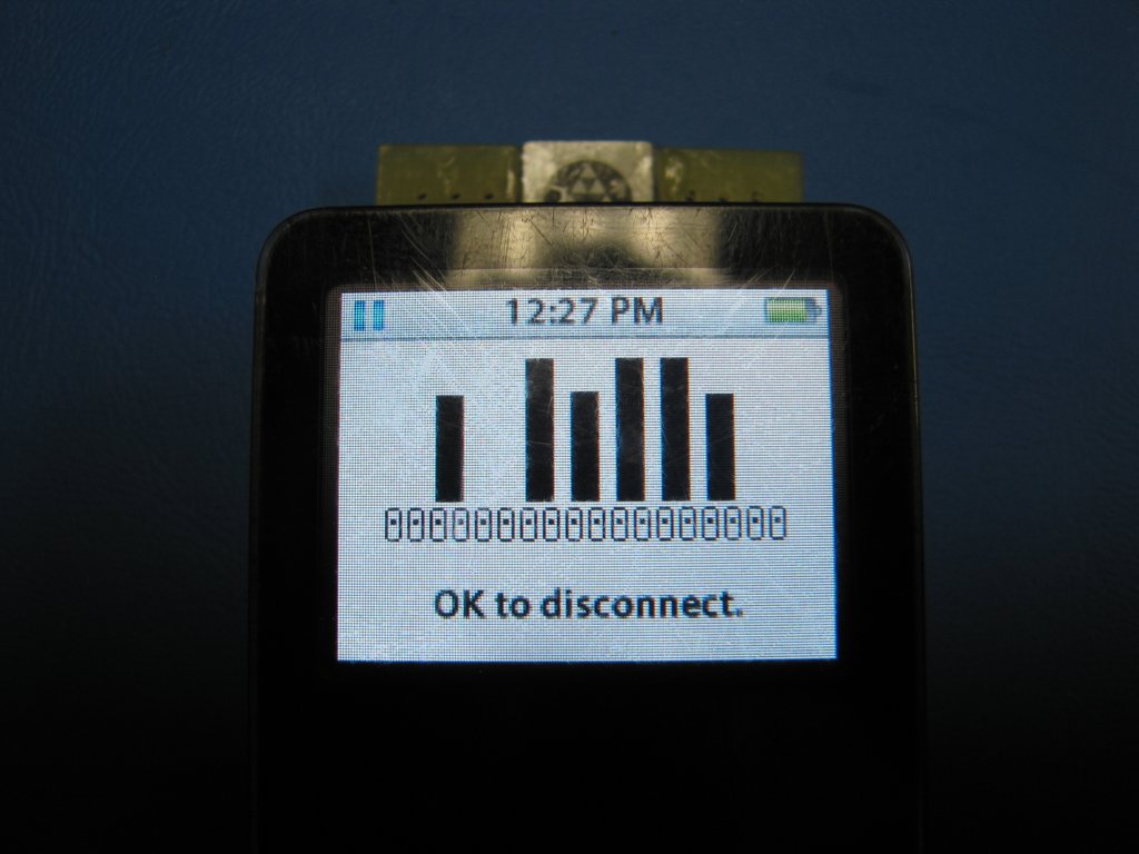
Figure 10: Signal Strength – Satellites acquired on left, actual signal strength on right. 2 digits per sat.
If interested, code examples in AVRGCC can be provided upon request. I would also like to re-iterate that this project only works on Non touchscreen iPods that have a dock connector (of course, non-screen iPods are omitted as well). The specifc Nemerix GPS is not necessarily required and can be substituted for any GPS that outputs NMEA senstences.
Last updated April 27th, 2009 - Copyright Enfinicorp.
Page manitained by: benkokes@hotmail.com